Impedance matching causes headaches for many engineers and electronics enthusiasts, yet it remains one of the most critical concepts for building efficient electrical systems. When circuits have mismatched impedances, signals reflect back instead of transferring properly, leading to power loss, distortion, and poor performance. Impedance matching balances the source and load impedances to maximize power transfer and minimize signal reflections in electrical circuits.
The process involves designing input and output impedances so they work together effectively. Without proper matching, high-frequency circuits suffer from standing waves, reduced signal quality, and wasted energy. This problem becomes more challenging as frequencies increase, making impedance matching essential for RF systems, transmission lines, and audio equipment.
Understanding impedance matching principles helps engineers design better circuits and troubleshoot existing systems. The techniques apply across many applications, from simple headphone connections to complex antenna systems. Getting impedance matching right means the difference between a circuit that barely works and one that performs at its full potential.
Impedance Matching Guide: Essential Principles and Applications
Impedance matching is a fundamental concept in electrical engineering and physics, crucial for maximizing power transfer, minimizing signal reflections, and ensuring optimal performance in various systems. This guide will delve into its essential principles and practical applications.
1. What is Impedance and Impedance Matching?
Impedance (Z) is a measure of the opposition to the flow of alternating current (AC) in a circuit. Unlike simple resistance (R) in DC circuits, impedance is a complex quantity that includes both resistance (the real part) and reactance (X, the imaginary part), which arises from inductors (inductive reactance, XL) and capacitors (capacitive reactance, XC). It is expressed as Z=R+jX, where j is the imaginary unit.
Impedance matching is the practice of designing or adjusting the input impedance of a load or the output impedance of a source to a desired value. The primary goals are typically:
- Maximizing Power Transfer: Ensuring that the maximum possible power is delivered from a source to a load.
- Minimizing Signal Reflection: Preventing signals from bouncing back from the load to the source, which can cause signal distortion and loss.
2. Essential Principles of Impedance Matching
a. Maximum Power Transfer Theorem
This theorem states that for a given source with a fixed internal impedance, the maximum power is transferred to the load when the load impedance is equal to the complex conjugate of the source impedance (ZL=ZS∗).
- For DC Circuits: Where reactances are zero, this simplifies to the load resistance being equal to the source resistance (RL=RS).
- For AC Circuits: If the source impedance is ZS=RS+jXS, then for maximum power transfer, the load impedance ZL should be RS−jXS. This means the resistive components must be equal, and the reactive components must be equal in magnitude but opposite in sign, effectively canceling each other out.
It’s important to note that while this maximizes power transfer, it does not necessarily maximize efficiency. At maximum power transfer, the efficiency is typically 50%, as half the power is dissipated in the source’s internal impedance.
b. Signal Reflection and Standing Waves
When a signal travels along a transmission line and encounters a change in impedance (an impedance mismatch), a portion of the signal energy is reflected back towards the source.
- Reflection Coefficient (Γ): This dimensionless quantity describes the proportion of an incident wave that is reflected from a discontinuity in the transmission medium. It is calculated as:
Γ=ZL+Z0ZL−Z0 where ZL is the load impedance and Z0 is the characteristic impedance of the transmission line. A reflection coefficient of 0 indicates a perfect match (no reflection), while a value of 1 (or -1) indicates total reflection. - Standing Waves: When incident and reflected waves combine on a transmission line, they create stationary patterns of voltage and current called standing waves. These waves do not propagate but appear to “stand” in place, with fixed points of maximum (antinodes) and minimum (nodes) amplitude.
- Voltage Standing Wave Ratio (VSWR): This is a measure of the impedance match of a load to a transmission line. It is the ratio of the maximum voltage to the minimum voltage along the line:
VSWR=VminVmax=1−∣Γ∣1+∣Γ∣ A VSWR of 1:1 indicates a perfect match (no reflections), which is the ideal scenario for most applications involving transmission lines. High VSWR values indicate significant reflections, leading to power loss, signal distortion, and potentially damage to components (e.g., in RF transmitters).
- Voltage Standing Wave Ratio (VSWR): This is a measure of the impedance match of a load to a transmission line. It is the ratio of the maximum voltage to the minimum voltage along the line:
3. Common Impedance Matching Techniques
Various techniques are employed to achieve impedance matching, often involving reactive components (inductors and capacitors) or transformers.
a. L-Networks
The simplest matching networks consist of two reactive components (one inductor and one capacitor) arranged in an “L” shape. They can transform a given impedance to another and are suitable for narrow-band applications. There are four basic L-network configurations depending on the series and shunt element placement.
b. Pi (π) and T-Networks
These networks use three reactive components arranged in a π (Pi) or T configuration. They offer greater flexibility than L-networks, allowing for wider bandwidth matching and independent control over the Q-factor (quality factor) of the circuit. They are commonly used in RF amplifier input and output matching.
c. Transformers
Transformers use magnetic coupling to transform impedances. The impedance transformation ratio is proportional to the square of the turns ratio (ZP/ZS=(NP/NS)2). They are effective for wide-band matching in audio and low-frequency applications and provide galvanic isolation.
d. Transmission Line Matching (Stub Tuning)
At high frequencies (RF and microwave), sections of transmission lines (stubs) can be used as reactive components for matching.
- Quarter-Wave Transformer: A section of transmission line with a characteristic impedance Zmatch=Zsource⋅Zload and a length of one-quarter wavelength (λ/4) can transform a load impedance to match a source impedance.
- Stub Tuning: This involves adding short-circuited or open-circuited sections of transmission line (stubs) in parallel or series with the main transmission line at specific distances from the load. The length and position of the stub are adjusted to cancel out the reactive component of the load and transform the resistive component to the desired value. Single-stub, double-stub, and triple-stub tuners exist, offering increasing flexibility.
e. Smith Chart
The Smith Chart is a graphical tool widely used in RF engineering to visualize and design impedance matching networks. It allows engineers to plot impedances, reflection coefficients, and VSWR, and to graphically determine the values of reactive components needed to achieve a match.
4. Applications of Impedance Matching
Impedance matching is critical in a vast array of electronic and other energy transfer systems:
- Radio Frequency (RF) Circuits:
- Antennas: Matching the impedance of an antenna to the transmission line (typically 50 Ω) and the transmitter/receiver output/input is crucial for maximum power radiation/reception and minimal reflections.
- Power Amplifiers: Ensuring the output impedance of an RF power amplifier matches the load (e.g., an antenna) maximizes power delivery and prevents distortion.
- Low-Noise Amplifiers (LNAs): While power transfer is important, LNAs are often matched for minimum noise figure rather than maximum power transfer, as noise performance is paramount.
- Filters and Mixers: Impedance matching is used to ensure efficient signal transfer between different stages of RF circuits.
- Audio Systems:
- Amplifiers and Loudspeakers: Matching the output impedance of an audio amplifier to the impedance of a loudspeaker (e.g., 4 Ω, 8 Ω, 16 Ω) ensures maximum power delivery to the speakers for optimal volume and sound quality. Mismatches can lead to reduced volume, distortion, or even amplifier damage.
- Microphones: Matching microphone output impedance to mixer/preamp input impedance is important for signal integrity and noise performance.
- High-Speed Digital Systems:
- In digital circuits with high clock speeds, traces on printed circuit boards (PCBs) behave like transmission lines. Impedance matching is essential to prevent reflections that can cause signal integrity issues, data errors, and electromagnetic interference (EMI).
- Power Delivery:
- While maximum power transfer (50% efficiency) is not always the goal for large-scale power distribution (where efficiency is paramount), impedance matching concepts are still relevant in optimizing power flow and minimizing losses in certain power electronics applications.
- Optics and Acoustics:
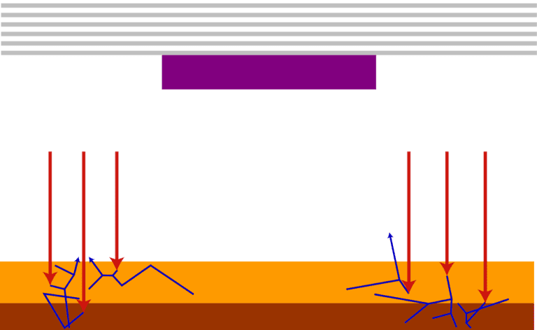
- The concept of impedance matching extends beyond electrical systems. In optics, it relates to matching refractive indices to minimize reflections at interfaces (e.g., anti-reflective coatings on lenses).
- In acoustics, it involves matching acoustic impedances to efficiently transfer sound energy (e.g., in loudspeaker design, acoustic horns, or ultrasound transducers).
Conclusion
Impedance matching is a cornerstone of efficient and reliable system design in electrical engineering and beyond. By carefully designing circuits to ensure that the source and load impedances are appropriately matched, engineers can achieve maximum power transfer, minimize signal reflections, reduce distortion, and ultimately enhance the overall performance and efficiency of electronic and other energy-transfer systems. Understanding the principles of maximum power transfer, reflection, and standing waves, along with the various matching techniques, is essential for anyone working with AC circuits and transmission lines.
Key Takeaways
- Impedance matching maximizes power transfer by balancing source and load resistances in electrical circuits
- Mismatched impedances cause signal reflections that reduce efficiency and create distortion in electronic systems
- Common applications include transformers, transmission lines, antennas, and audio equipment where proper matching ensures optimal performance
Frequently Asked Questions
Engineers often face specific challenges when implementing impedance matching in circuits. These questions cover calculation methods, transmission line behavior, amplifier design considerations, practical examples, audio system consequences, and standard formulas.
How can one calculate the correct impedance matching for a specific circuit?
Engineers calculate impedance matching by first measuring the source and load impedances. They use network analyzers to determine the exact values at operating frequencies.
The calculation requires finding a matching network that transforms one impedance to another. For simple cases, engineers use the formula Z = R + jX, where R is resistance and X is reactance.
Smith charts provide a visual method for complex calculations. Engineers plot the source and load impedances on the chart. They then design networks to connect these points.
L-networks work well for moderate impedance ratios. The engineer calculates the required inductance and capacitance values using standard formulas. More complex networks like pi or T configurations handle larger impedance differences.
What is the function of impedance matching in transmission line applications?
Transmission lines require impedance matching to prevent signal reflections. When impedances mismatch, part of the signal bounces back toward the source.
The characteristic impedance of the transmission line must match both source and load impedances. Common values include 50 ohms for RF systems and 75 ohms for video applications.
Standing waves form when reflections occur. These create voltage and current variations along the line. The standing wave ratio measures how well the system matches.
Matching networks placed at line ends eliminate reflections. Stub tuners and quarter-wave transformers provide common solutions for transmission line matching.
What is the role of impedance matching in amplifier design?
Amplifiers need proper impedance matching for maximum power transfer. The input matching network connects the signal source to the amplifier efficiently.
Output matching transforms the amplifier’s high impedance to the load impedance. This ensures the amplifier delivers full power to the load.
High-power amplifiers require careful impedance design. A 100-watt amplifier with 50-volt supply needs approximately 12.5-ohm load impedance for maximum efficiency.
GaN amplifiers present unique matching challenges. Their low impedance outputs require specialized matching networks. Engineers must consider both fundamental and harmonic frequencies.
Can you provide an example of how to perform impedance matching in a practical scenario?
Consider matching a 10-ohm source to a 50-ohm antenna at 100 MHz. An L-network provides the simplest solution for this 5:1 impedance ratio.
Calculate the required Q factor using the formula Q = sqrt((R_high/R_low) – 1). For this example, Q = sqrt((50/10) – 1) = 2.24.
The series reactance equals Q times the low impedance: X_series = 2.24 × 10 = 22.4 ohms. At 100 MHz, this requires a 35.6 nH inductor.
The parallel reactance equals the high impedance divided by Q: X_parallel = 50/2.24 = 22.3 ohms. This needs a 71.4 pF capacitor at 100 MHz.
What are the potential consequences of failing to properly match impedance in an audio system?
Mismatched audio systems suffer from poor frequency response. Certain frequencies become emphasized while others get attenuated. This creates unnatural sound reproduction.
Power transfer efficiency drops significantly with impedance mismatches. A 4-ohm speaker connected to an 8-ohm amplifier output receives less power than designed.
Amplifier stability can become compromised. Some amplifiers oscillate or produce distortion when connected to mismatched loads. Protection circuits may activate to prevent damage.
Signal reflections in audio cables cause timing issues. Digital audio systems are particularly sensitive to impedance mismatches on transmission lines.
What are the typical methods or formulas used to achieve impedance matching?
L-networks provide the simplest matching solution. Engineers use the formulas X_L = sqrt(R_high × R_low) and X_C = R_high × R_low/X_L for basic calculations.
Pi and T networks handle more complex matching requirements. These configurations offer additional flexibility but require more components and calculations.
Quarter-wave transformers work well at single frequencies. The characteristic impedance equals sqrt(Z_source × Z_load) for maximum power transfer.
Transformers provide impedance transformation using turns ratios. The impedance ratio equals the square of the turns ratio: Z_ratio = (N_primary/N_secondary)².


